Namaste Mouse Fondlers and welcome to this installment of "Designing Hollow Wooden Surfboard Templates" using AKU Shaper and Hollow Board Template Maker software. Now there may some old school wooden surfboard board building tradey types out there who may not be too fond of this newfangled computer technology stuff and right now you are cringing at the thought of mind wrestling with your PC or laptop. I can understand that, having come from a long line of tradesmen myself. After all, my Dad, Mr. Wood Buddha Senior, rest his soul, was an old school tradey with thick sausage fingers and calloused hands the size of dinner plates that could crush an elephant's testicles. He never really understood what all the fuss over computers was about. But I have to say that having designed a wooden surfboard the old fashioned way using paper, pencils and rulers and also using computer aided design software like AKU Shaper, that there are some definite benefits to computer design. It is accurate, it is fast (once you get some practice) and the template files can be printed and shared easily with other wooden surfboard builders from all over the world. The templates can also be converted into other formats such as DXF and DWG files that can be used with CNC machines to provide automated cutting of the templates.
I think that part of the problem with learning how to use some new software is that sometimes the user documentation is often a little light on and doesn't always include tutorials on how to use the software in real life situations. I'm always up for a challenge so I thought I would put together a "Quick Start" tutorial with a slant on hollow wooden surfboard template design. So here goes.
Now, before you jump down my throat to give me a reverse ass-hole-ectomy regarding my "documentation is a little light on" comment, I would just like to say that this is a generalisation and not in any way directed at the wonderful folks at AKU Shaper and the designer of HBTM who have very generously provided us with free versions of their software with help support built in. If you do like these pieces of software and want to show your appreciation, you can always buy the paid version of AKU Shaper or make a donation to JedAil the developer of HBTM.
Another point I wanted to make was that I am not the guru subject matter expert on AKU Shaper. There are probably more capable drivers of this software than me. But I have spent an inordinate amount of time using this software from the perspective of a part-time, underpaid wooden surfboard builder. My motivation is to try and cut down the learning curve for others and make the learning process a little easier.
So without further adieu, let's get cracking shall we.
So by now you've probably gathered that we will be using two software programs to do this design, AKU Shaper 1.18.000 and Hollow Board Template Maker (HBTM) 2.0.10. We'll start with AKU Shaper.
Note: As of April/May 2014 the Java version of AKU Shaper (1.18.000) is no longer working due to a server and security issue. You will need to use the latest licensed version of AKU Shaper.
Jimmy Freese from AKU Shaper writes:
Yes we are having an issue with our .jnlp version of the software related to server and security. We're working to fix that. Java/Oracle has made things difficult as that is an older version with a lot of older libraries.
Feel free to download the latest Version of AKU at
Firstly, we need to find a picture of a board plan shape and profile (rocker) that we like. We could photograph a board or find a picture on the Web. For the purposes of this tutorial I've used Google images and found an image of a rounded pin tail that I like. I've saved the board image to my laptop and then edited it in Microsoft Paint to make sure that the nose of the board is pointing to the right hand side of the computer screen. This will be the board image which we will base our design
on. Here’s one I prepared earlier. I had to flip the board 90 degrees to line up the nose and tail with the board direction in AKU.
Next, we'll fire up AKU Shaper. This may take a few minutes so please be patient.
You should end up with a screen like this.
Now at this point I will mention that we will be using the free Java version of AKU Shaper 1.18.000. The software is also available for purchase as a Windows, Apple or Linux compatible application. The paid version of AKU Shaper is the latest release and has extra features. The Java version of AKU Shaper does not run well under newer versions of the Java Runtime Environment.
This is from the AKU Shaper website. "A number of recent java updates have done their best to destroy this release. We have put a lot of time into AKU Shaper 2.0 addressing the issues and adding a number of improvements. We will keep this version running as long as possible but we are now longer actively supporting it. If you're running into problems try downgrading to Java version 6".
Older versions of Java SE Runtime Environment are available on the Oracle archive. Be aware that older versions do not have recent security updates.
I am also running Windows 7 on my laptop.
Before we get back into the tutorial, I wanted to mention that AKU does have a help option that has some good reference information. There are also some tutorials to get you started as well. Click on the "Help" menu option and then "Help" again. There is also a reference card in the categories.
Before we get back into the tutorial, I wanted to mention that AKU does have a help option that has some good reference information. There are also some tutorials to get you started as well. Click on the "Help" menu option and then "Help" again. There is also a reference card in the categories.
The Help menu.
Click [File – New – 7’6” generic Shortboard] in the drop down box and click OK. The board size template that is chosen will depend on what size board is required. We'll select the size that is closest to the final size of board, about 8'. Remember we can always change the board size at any time while we are designing in AKU.
Click [File – Image Board –
Outline], we choose the directory where we saved our board plan and profile image. We select
the plan image and click OK.
The dialogue box for aligning the image board.
To line up the image board, we hold down the “n” key on our keyboard, hold our mouse pointer over the tip of the board nose on the image and left click our mouse. For the tail, we hold down the “t” key of our keyboard, hold our mouse pointer over the tail of the board on the image and left click our mouse.
The nose aligned.
The tail aligned. The image is hiding behind the board outline.
Designing the Outline
The next step of the process is to adjust the board outline. We'll do this by moving the bezier points (blue dots) which are located on the board outline. Bezier
points can be added to the bottom curve of the plan shape to get it match the
shape of the image board. Existing bezier points can also be moved.
To move an existing point, we hover the mouse pointer over it, hold down the left mouse button, and move the point to
where we want it. We release the mouse button to release the point when we’re
happy with its position. We can also click on the bezier point and use our arrow keys to move it around.
We can add Bezier points by clicking on the “Add
Point” button on the menu bar, hovering our mouse point over the section
of the bottom board line where we want to position the point and clicking the
left mouse button.
We can change the angle of the board outline by moving the
red and yellow tangent points associated with the blue Bezier point.
Play around and and don't be afraid to make mistakes. It’s a great
way to learn. You can always use the "Undo last curve change" keys (curved arrows) on the menu bar to undo any changes you've made.
Tip: Use the minimal number of
Bezier points to adjust the outline of your board. This will give gentle
flowing curves and minimise any lumps and bumps.
The outline adjusted. An extra bezier point has been added towards the nose of the surfboard.
To hide the image board, we click on [Show/Hide] on the menu bar, and uncheck the "Show Image Board" button.
To avoid the disappointment of losing your work, always remember to save your design regularly!
Next we highlight the original bezier point at the top of the tail. Notice that the yellow and red tangent points aren't in a straight line. Looking at the point control zone in the lower right hand corner, there is a check box there called "Cont". If this box is checked then the the red, yellow and blue points of the bezier are all in a continuous straight line. This bezier end point at the tail normally has "Cont" unchecked. We check this box and move the red tangent point so that all three points are in a straight vertical line. We can highlight the blue point and use our down arrow key to move it down the tail of the profile.
Now that we've completed the outline and profile design and we can now start working on the rails through the slices view.
Next we'll add a slice to that same position. Click [Slices - Add a New Slice] in the menu bar. An "Add a Slice" window should appear. Type 400 in the "Type X-coordinate?" box and press OK. A new slice will be added at 400 mm from the tail.
Using the bezier and tangent points, adjust the outline of the added slice with the intermediate slice outline (white outline) until they both match. You may not be able to get it perfectly aligned but try to get it as close as possible. Use the "Zoom" button to view the slice lines close up.
We repeat this process until we have added slices at 200 mm intervals for the entire length of the board. We also add additional slices at 100 mm from the tail and nose as well. Now we delete the original 5 slices located at the board centre, 300 mm from the nose and the tail and right near the nose and the tail. We do this by highlighting each of these slice lines on the board outline (one at a time) and clicking the [Slices - Delete Current Slice] menu option.
To avoid the disappointment of losing your work, always remember to save your design regularly!
Designing the Profile
Let's design the profile next. There are two elements to this, a top curve and a bottom curve. To adjust the top of the profile we click on the "Top" tab.
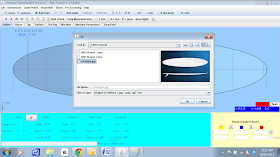
To load the image of our board profile, we click [File – Image Board – Profile], choose the directory where we saved our board image file. We select the image and click OK. See the screens below.
Loading the profile image.
Choosing the image file.
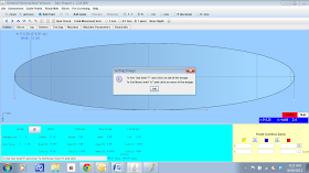
The nose and tail alignment dialogue box. Click OK.
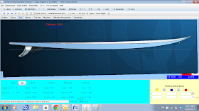
The profile image loaded.
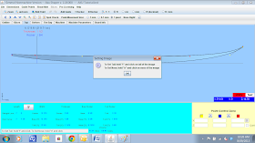
Aligning the nose. We hold down the “n” key on our keyboard, hold our mouse pointer over the tip of the board nose on the image and left click our mouse.
And the tail. We hold down the “t” key on our keyboard, hold our mouse pointer over the tail of the board on the image and left click our mouse. The nose and tail alignments can also be changed on the bottom profile. We click on the "Bottom" tab and follow the same process in that view. We can now make adjustments to the blue bezier points to match the surfboard profile with that of our board image. We can add more bezier points if required.
Tip: Try to align the bottom profile of your board image with the white horizontal guide line on the screen.
Tip: Use the "Zoom" menu tab button for detailed adjustments at the nose and the tail. "Unzoom" reverts back to the original view. When in the "Zoom" view, the board can be moved around the screen using the keyboard arrow keys. Click on the "Zoom" button in the menu bar and draw a viewing rectangle by holding the right mouse key and dragging the mouse pointer.
The top and bottom profiles have been lined up reasonably close to the board image. There's still some fine adjustments needed on the nose and tail detail. We'll do those now.
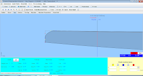
Starting with the Top profile at the tail we round that off with a slight radius. You'll notice that I've hidden the background image board so that it's easier to see our board.
First we add a bezier point to the top profile line near the tail. We do this in the "Top" profile view with the design "unZoomed". If we try to add a bezier point while the view is "Zoomed" AKU doesn't seem to like it. I think the mouse pointer needs to be located exactly over the profile line.
Next we highlight the original bezier point at the top of the tail. Notice that the yellow and red tangent points aren't in a straight line. Looking at the point control zone in the lower right hand corner, there is a check box there called "Cont". If this box is checked then the the red, yellow and blue points of the bezier are all in a continuous straight line. This bezier end point at the tail normally has "Cont" unchecked. We check this box and move the red tangent point so that all three points are in a straight vertical line. We can highlight the blue point and use our down arrow key to move it down the tail of the profile.
We end up with a radius curve like in the picture above. The tangent points can be adjusted to fine tune the curve.
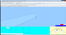
Now we do the same with the nose of the surfboard. We "unZoom" the view and add a new bezier point near the nose by clicking on the "Add Point" button in the menu, and positioning our mouse over the top profile line near the nose. We make sure that the point we've added is reasonably close to the nose of the board. This is where the radius of the curve will start.
Next we highlight the original bezier point at the top of the nose and check the "Cont" box in the point control zone in the lower right hand side of the screen.
We move the yellow or red tangent point so that all three points are in a straight vertical line.
Then we highlight the blue point and use our down arrow key to move it down the nose of the profile to create a curve.
Now we'll work on the nose and tail of the bottom profile.
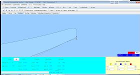
We click on the "Bottom" tab to work on the bottom profile and "Zoom" in on the surfboard nose. We add a new bezier point near the surfboard nose on the bottom profile line and highlight the original blue point on the bottom profile line at the nose.
Looking at the point control zone you'll notice that this blue bezier point doesn't have a red tangent point. There is only a yellow tangent point so there's no need to check or uncheck the "Cont" box. The behaviour of this bezier point is the same regardless.
We move the yellow tangent point to create a vertical line with the blue point.
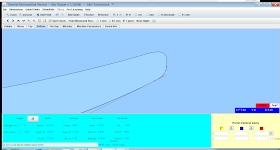
And move the highlighted blue bezier point up using the up arrow key to create a radius curve.
We'll leave the bottom of our surfboard tail without a radius and keep this edge sharp. This is fairly common in surfboard designs and allows for quick release of water at the tail.
We can also change the nose and tail rocker by clicking on the "N Rocker" and "T Rocker" options in the menu bar, clicking your mouse pointer in the design section of the screen and use the up and down arrow keys to raise or lower the nose and tail.
Designing the Rails and Slices
Now that we've completed the outline and profile design and we can now start working on the rails through the slices view.
Click on the Slices tab. To highlight the slice we want to work on, we click on the slice line on the board outline, above the slice image. The slice line will change colour to red and the slice image will appear in the lower section of the window. In the picture above, we are looking at the centre slice. By default, AKU Shaper will place slices at the centre of the board, 300 mm from the tail and the nose and roughly 50 mm from the tail and the nose. We can make adjustments to a slice by moving blue bezier points and changing the position and length of the red and yellow tangent points. We can also add new bezier points as well. It's best to use the least number of bezier points as this will give smoother lines.
To move a slice, highlight the slice line on the board outline. In this case we highlight the slice at 1676.4 mm from the surfboard tail. The slice line changes colour to red.
Click [Slices – Move Current Slice] in the drop down box.
A dialogue box will appear. We enter the new position for the slice and click OK. The slice will move to the new position. In this case we will move the slice 300 mm from the nose which is the board length 2286 mm - 300 mm = 1986 mm.
The new slice at 300 mm from the nose.
Some other things we can do in "Slice" view.
Adding a new slice - Click on [Slice - Add a New Slice] and enter the position of the new slice from the tail of the surfboard.
Deleting a slice - Highlight the slice we want to delete. Click on [Slice - Delete Current Slice] and the current slice will be deleted. Be careful using this as no warning dialogue box appears.
To view the intermediate slices between the main slices, hold down the shift key and move the mouse over the surfboard outline. We do this in the Slice view. The intermediate slices will appear as white outlines.
Adjusting Surfboard Dimensions
We're on the home straight. We've designed our board outline, rocker and slices and now all that's left is to fine tune the measurements. One of the key surfboard measurements we can change indirectly is the board volume. We do this by changing the length, width and thickness of the board. If we look at the very bottom centre of the AKU screen, we can see the board volume is measured in litres or beers. Personally I find the metric system confusing so it's all about the beers for me.
We can click on the "Change the Length and Width" button at the bottom left hand side of the window. The "Change Length Width Thickness" dialogue box will appear. In this case the measurements are in metric units. The measurements can be changed to imperial units by clicking the "ft" measurement radio button in the menu bar.
Changing the surfboard length, width and thickness.
In the picture above, we've changed the measurements to "ft" imperial. The length has been changed to 8'6', the width to 22" and the thickness to 3". This has changed the volume to almost 62 litres. The screen shows the original board outline and the new board outline for comparison. When designing a surfboard in AKU Shaper I will often toggle between imperial and metric units. I understand the length, width and thickness in imperial measurements better, however when I am working on slice placement I prefer metric. I struggle with fractions sometimes.
We can view the board in 3D by clicking on the "The Bay" tab. There are lots of shortcut keys that can change the way the board appears in this view.
To change the angle of our view in 3D mode, we use our arrow keys. We can also use our mouse for this by holding down the left mouse button and moving the mouse pointer around the bay. The mouse wheel zooms the screen in and out.
Pressing the "v" key toggles the board views between solid, sliced, wired and curves. The "f" flips the board over and the spacebar toggles the curves on and off.
Press "h" for other help options like the various board modes.
Making Templates
Now let's get to the nitty gritty and start on the templates. If we were to use this board file with HBTM we'd end up with a template that only has 5 slices or ribs. Not ideal. What we want is a template that has slices spread out at even intervals over the board length. The distance between slices is a personal choice. I like to use 200 mm for long boards and 150 mm for shorter boards. Some wooden board builders go even shorter at 100 mm. For this tutorial we'll use 200 mm as the distance between slices and we'll add an two additional slices 100 mm from the nose and the tail.
First we'll save our board with a new file name and use this for adding the additional slices and making the templates. Let's call it "AKU Tutorial Template.brd". That way, if we make a pig's breakfast of it we can always reload our original board file.
When AKU Shaper adds a slice, the new slice added, takes its attributes including rail shape from the nearest adjacent slice. What does this mean? If we add a slice without adjusting its shape, the result will be a surfboard design where the flow of the curve length ways does not match our original 5 slice design. In other words the flow will have lumps and bumps. To maintain a continuous flow of the board shape from nose to tail we need to be thoughtful about how we add slices and it does involve some adjustment of the added slices. So how do we do this? We use a feature called intermediate slice view and use this as a guide to adjust our added slices. The intermediate slice view (hold down the "Shift" Key and the left mouse button and drag your mouse across the board outline from tail to nose in "Slices" design mode) shows us what the slice should really look like at any point on the board. The "real" slice shape appears as a white slice outline around the slice view at the bottom of the design pane. We will use this intermediate slice outline as a guide to adjust our new added slices.
Click on the "Slices" tab to get into slice design mode. Click on the "mm" radio button in the menu tab. So let's add a slice at 400 mm from the tail. Firstly, we hold down our "Shift" Key and the left mouse button and drag our mouse across the board outline from tail to nose until the location or X-coordinate value is 400 mm. Release the left mouse button. Don't worry too much if it's not exactly 400 mm. Plus or minus a millimetre or two is okay.
Next we'll add a slice to that same position. Click [Slices - Add a New Slice] in the menu bar. An "Add a Slice" window should appear. Type 400 in the "Type X-coordinate?" box and press OK. A new slice will be added at 400 mm from the tail.
Using the bezier and tangent points, adjust the outline of the added slice with the intermediate slice outline (white outline) until they both match. You may not be able to get it perfectly aligned but try to get it as close as possible. Use the "Zoom" button to view the slice lines close up.
In the picture above, the bezier point at the top of the slice line is highlighted and moved to adjust this section of the slice. Once we are happy with the slice shape we can add the next slice at 600 mm.
We'll hold down our "Shift" Key again and the left mouse button and drag our mouse across the board outline from tail to nose until the location or X-coordinate value is 600 mm. We release the left mouse button. Don't worry too much if it's not exactly 600 mm. Plus or minus a millimetre is okay.
Click [Slices - Add a New Slice] in the menu bar. An "Add a Slice" window should appear. Type 600 in the "Type X-coordinate?" box and press OK. A new slice will be added at 600 mm from the tail.
A new slice is added at 600 mm and appears in the slice design pane.
Using the bezier and tangent points, we adjust the outline of the added slice with the intermediate slice outline (white outline) until they both match. The picture above shows the slice before adjustment.
The slice after adjustment.
The final design should look like the picture above with slices positioned every 200 mm and two additional slices 100 mm from the tail and the nose.
Now fire up HBTM at the following link http://jedail.free.fr/programs/HBTM.jnlp. This may take a few minutes.
We click [File - Open] and select our BRD file which is called "AKU Tutorial Template.brd". Click "Open" and the file will be loaded when the "APS3000 file loaded successfully" dialogue box appears. Click OK.
Now we can alter the template variables to suit the style of surfboard we are going to build. In this case, skin thickness is 6 mm (0.6 cm), the rail type is solid, the rail thickness is 20 mm (2.0 cm) and this will exclude the first rail band or outer frame rail band, spine thickness is 6 mm (0.6 cm), rib thickness is 6 mm (0.6 cm) and the outer frame thickness is 5 mm (0.5 cm). We'll leave the notch position set as "Bottom".
Click [File - Generate Full Template].
HBTM will ask you to save the template file to a directory. Click Save.
The template is generated successfully. Click OK.
To view the template, go to the directory where the template was saved and double click on the PDF file in this case "AKU Tutorial Template_Full.pdf". If you have Adobe Reader or some other PDF viewer the file will open and you will be able to view and print it.
The template generated and ready for printing.
If you are wanting to produce templates for the bead and cove rail method, make sure the Rail Type - Strip Planking Rail radio button is checked. The slices in the template will have rounded ends instead of squared ends.
If you have any questions, feedback or improvements just drop me an email at woodbuddha1@gmail.com
















This comment has been removed by a blog administrator.
ReplyDeleteThanks so much for that info, great help. Just a quick question, what size do we print the PDF at. Cheers
ReplyDeleteHi Travis,
DeleteThe PDF template that's produced by HBTM is actual size and tends to be very large. You can print the templates out a few ways.
1. You can get full size architectural print outs done at a specialist print shop but they tend to be pretty expensive.
2. If you have a printer that supports poster or tile printing you can print out the template over multiple A4 or A3 sheets and glue them together.
3. There is a freeware program called PDF Tile Printer (http://www.lucubration.com/pdf-tile-printer) that prints over sized PDF documents to standard sheet sizes. I haven't used it myself but I know of wooden board builders that do.
Hope this helps.
WB
The program template maker hollow plate leaves me open
ReplyDeletehttp://jedail.free.fr/programs/HBTM.jnlp. it is work on mac?
ReplyDeleteNope
DeleteOh brother. I am so stoked and appreciate your time that you spent to create this handbook. really really good job. Thank you very much.
ReplyDeleteI want to do a board as well. It's a kind of performance fish shortboard hybrid. It has a swallow tail and I couldn't figure out how to do the swallow with the generic board samples. Could you help me and tell me how that works?
Cheers and blessings
Jan
Hi Jan, the AKU Shaper software doesn't handle swallowtail type tails very well. I've designed Fish style boards with a square tail and cut the swallow tail into the board during construction.
ReplyDeleteThank you for the quick answer. I think that will be the way then. Again, thanks for your time and work. Charing is caring. cheers
DeleteWOW! thank you very much for this. Easy to follow and a great way to start using the program and building boards! Can't thank you enough... my 5' 3" mini simms is ready to print!
ReplyDeleteTake lots of photos so I can post your build on my blog.
ReplyDelete
ReplyDeletehello, someone can tell me how I can download the hollow board maker template ?? already I tried everything even stirring the security of Java 8.0 and can not install the program
love the look of this!!! how did it turn out? I just got an X-Carve and would love to try cutting out template pieces. Would you be able to share the CNC file? =)
ReplyDeleteThis design was just to show folks how to design templates. I haven't had the opportunity to build it. I don't have a CNC file available.
Deletehonestly, than you so much for this.
ReplyDeleteGreat article I'm very thankful for!
ReplyDeleteI'm starting a 7'5" as a summer project, but (HELP/tips) I cannot make Hollow Board Template Maker to work. As soon as I clic on the link, I get a .jnlp file (which I can't open). Any tips from here will be heartly thanked.
Peace!
HBTM is a java program and you need to have the Java Runtime Environment installed on your computer for it to work. http://www.oracle.com/technetwork/java/javase/downloads/jre8-downloads-2133155.html
DeleteThanks Buddha! For potential future references: HBTM runs on Java 7 (after setting security level to "Medium") Java8 starts from "High", which blocks HBTM.
DeleteJ8 must be deleted from computer before executing.
Hope it helps :)
Thanks for the tip Guille
DeleteI downloaded the Java Runtime Environment, but when I try to run the HBTM it says that security is blocking it from being opened. They have done away with the Medium security setting in this latest version. Ideas?
DeleteThis is just what I needed!
ReplyDeleteI now have a full printable template for my new 5.6 "Mitu" I'm so excited to get started!!
Hi Jens, we are making the same boards, but a 5.4 and 5.10 :)
Deletecheers/ Johan Wiklöv
Hi, I`m having trouble with the PDF file, the PDF generated by HBTM is 0kb, I did everything as you said. Could you help me?
ReplyDeleteEmail me your BRD file at woodbudda1@gmail.com and I'll have a look at it for you.
ReplyDeleteplease check your mailbox,i sent you the email on 10/24
DeleteSorry, I gave you the wrong email address. Try woodbuddha1@gmail.com
DeleteNo problem. Thanks
DeleteIs this process available with windows 10? or would i have to buy an older computer to get it to work?
ReplyDeleteAnybody ever have the problem with HBTM that the points in the ribs come out all twisted and wierd. I've tried everything to fix it but end up pulling it in illustrator and just recreating it. It's a lot of extra work. any help would be great. thanks!
ReplyDeleteThis comment has been removed by a blog administrator.
ReplyDelete